Composite Layers
here we will discus the method for creating islands and holes. The most powerful, and easiest method to achieve this, is via Composite Layers. A composite layer is one that is made up of many other layers, with each individual layer having its own properties. Composite layers are the best method when designing in a CAD package that doesn’t support the theory of holes, such as AutoCAD.
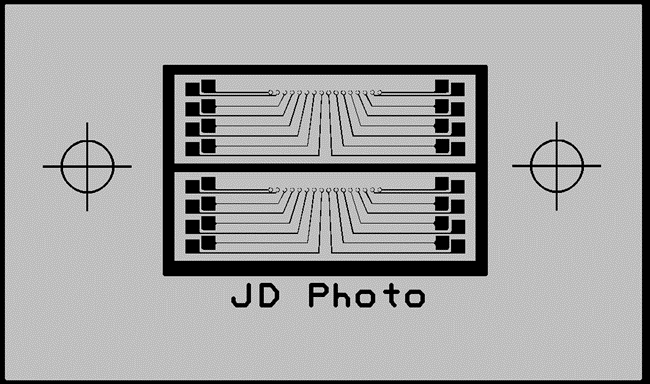
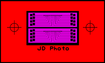
The picture shows a 6 layer composite design. In the following section you will see how the layers are built in our own internal CAD formatting. We will describe how to create this affect based on an AutoCAD design. This sample design will assume a mixture of both Darkfield (opaque) and Lightfield (clear) parts on one pattern, with concentric parts and using borders.
STAGE 1: WHY COMPOSITES?
AutoCAD doesn’t understand the property of a filled shape – or polygon. The nearest it comes is by using a zero width closed polyline – a line that has no actual width, but represents a boundary that is closed. Our imaging systems use these boundaries to “fill in” the area – so in effect, this boundary represents an area that needs filling. You can have as many of these on the design as you need, but there are times when you want to also have things ‘inside’ this boundary... this is where composites come in. AutoCAD does have a ‘solid fill’ that can represent a filled area, but even this wouldn’t be able to cope with ‘holes’ in the design. Some people refer to this as ‘paint’ and ‘scratch’. The first item is ‘painted’ on the design and the second item is ‘scratched’ away from it.
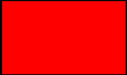
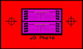
 This is what the customer designed in Autocad
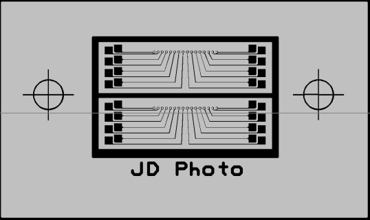
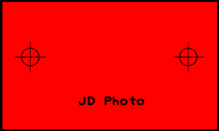
 This is how the pattern will look when imaged
if the above design was put through to be imaged, the result would be one large covered block. This is because we had to fill the polygons, but every polygon was on the same layer so the outer one flooded over the inner data (don’t worry, we would obviously spot something this bad in CAD , and you would also see it on the PDF checkplot, but we will use this example as an extreme!)
To image the pattern correctly, the AutoCAD design needs to be split into multiple layers. Each group of items that sit “inside” a polyline boundary (P-line) needs to be placed on a separate layer, in order for them to be painted and scratched (Dark or Clear).
In addition to setting layers depending upon polarity (dark/clear), we also need to consider that each different group of entities also needs to be placed on their own separate layers depending on how we deal with them, because we can only automatically process items on a layer by layer basis, and not an item by item basis (this can actually be done on an item basis, but that would be controlled manually and not automatically, and therefore there would be a CAD processing cost involved)
When we process a layer, we have to say whether it’s Dark or Clear, and we have to also tell our system whether to FILL or UNFILL the layer. If you take the example design above, we cannot FILL the layer with the targets on because otherwise the whole circle would be completely filled and loose the centre crosshair. Similarly with the text – if we chose to fill this layer then the letter ‘D”, “P”, “O” etc would become filled and unreadable. It’s because of this reason that these items must be grouped onto their own layer – a layer that is not filled. If these items have been drawn in AutoCAD with a zero width line (which is the usual case), then you need to specify to us a line width to use. Again, this is on a layer by layer basis so if you needed the draw width/line of the target to be different to the linewidth of the text, they would have to go on separate layers. In this design, we are going to assume the same linewidth.
STAGE 2: SPLIT THE LAYERS
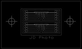
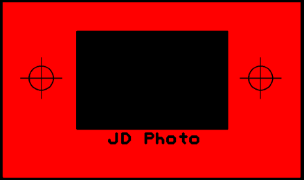
Take each group of outer items and move them to their own layer. In the design below, the outer rectangle has its own layer, the text and targets are placed on a 2nd layer, the inner boundary is placed on a 3rd layer. The device boundary makes up the 4th layer, the device itself makes the 5th layer, and the final layer is made up of the inner holes in the circuitry pads.
STAGE 3: ANNOTATE THE POLARITY AND THE FILL STATUS
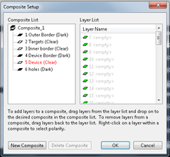
Once the layers have been split, it’s then just a simple task of assigning the layer order, the layer polarity, and the fill status of the layer. Here is how the layers are built...
 1… Outer Border, Filled, DARK
 2 …Targets, Linewidth 0.5, CLEAR
 3 …Inner Border, Filled, CLEAR
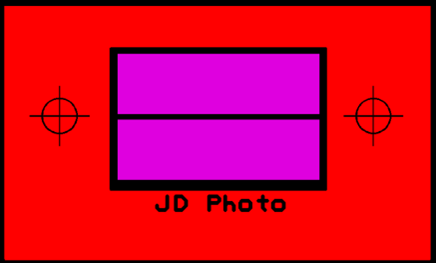 4 …Device Border, Filled, DARK
 5 …Device, Filled, CLEAR
 6 …Holes, Filled, DARK
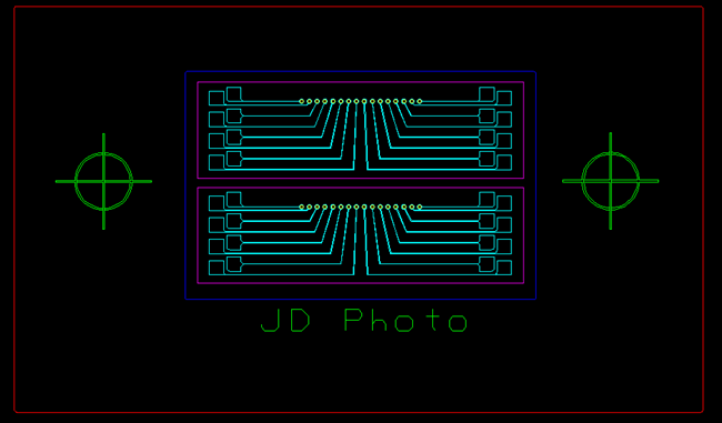
STAGE 4: THE FINAL DESIGN, PUT TOGETHER AND VIEWED BY OUR ENGINEERS.
The final stage is for our engineers to put the design together, apply the properties and then create the fill patterns. This can be a complex procedure where full instructions have not been given, but the results are always checked by sending a PDF checkplot to the customer to act a final ‘proof’ before the mask is made.
The checkplot will show the how the pattern will appear when it is written – the data will be mirrored to reflect the view side as chosen by the customer, and the polarities will have been set to create the final Clearfield or Darkfield pattern that is required (however, don’t take the quality of line edges on the PDF to represent how the mask will look, because PDF files cannot resolve these features adequately)